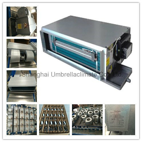
Ceiling Concealed Fan Coil Unit (HVAC Terminal FCU)
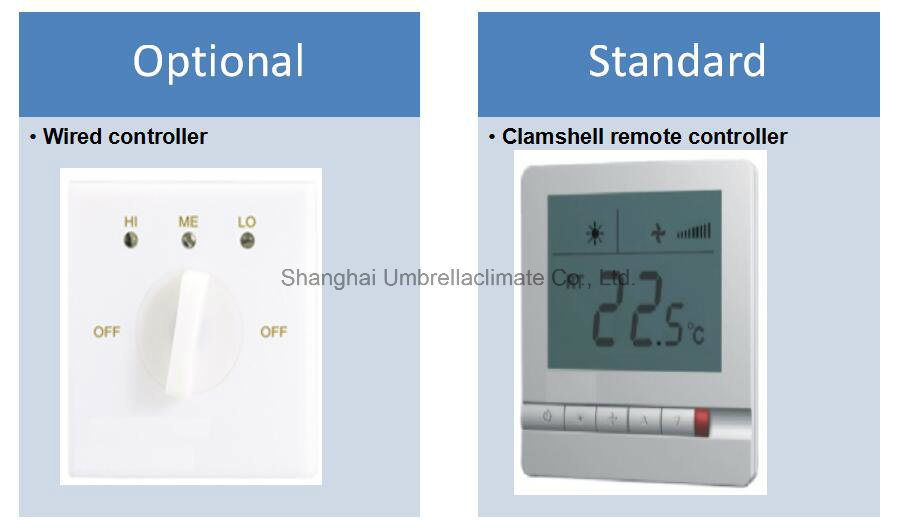
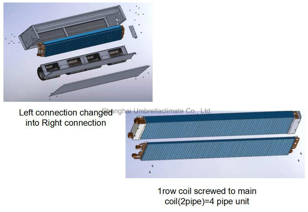
Minimizes Costs- Maximizes Flexibility- Optimizes Distribution √  3-speed centrifugal fan statically and dynamically balanced (for AC version) √  EC Motor with modulating 0-5 V DC Input(for EC version) √  Auxiliary Electric Heater Element for installation On-site or In-stock √  Interchangeable left/right side coil connections √  Auxiliary 1 row heating coil for installation On-site or in-stock √  12,30 and 60 Pa External Static Pressure(ESP) models available (for AC version) √  Variable External Static Pressures(ESP)up to 60 Pa(for EC version)
a. Cooling mode:                                           b. Heating mode:                                 - Return air temperature: 27C DB/ 19C WB.                         - Return air temperature: 20C.         - Inlet/ outlet water temperature: 7C/ 12C.                          - Inlet water temperature: 50C.                                                                 - Water flow-rate: same as cooling mode  Â
Â
Ceiling Concealed Fan Coil Unit (HVAC Terminal FCU)
Minimizes Costs- Maximizes Flexibility- Optimizes Distribution √  3-speed centrifugal fan statically and dynamically balanced (for AC version) √  EC Motor with modulating 0-5 V DC Input(for EC version) √  Auxiliary Electric Heater Element for installation On-site or In-stock √  Interchangeable left/right side coil connections √  Auxiliary 1 row heating coil for installation On-site or in-stock √  12,30 and 60 Pa External Static Pressure(ESP) models available (for AC version) √  Variable External Static Pressures(ESP)up to 60 Pa(for EC version)
Shijiazhuang Naipu Pump Co.,ltd is a professional manufacturer of all type of horizontal centrifugal slurry pumps. Our horziontal centrifugal slurry pumps including:NP-AH,NP-AHR,NP-HH,NP-M which are designed for handing highly abrasive,high density slurries in the metallurgical,mining,coal,power, building material and other industrial department,etc.The pumps of this type also maybe installed in multistage series.
NP-G,NP-GH gravel and sand slurry pumps are designed for continously handling the most difficult higher abrasive slurries which contain too big solids to be pumped by a common pump. they are suitable for deliverying slurries in mining.Explosive-sludge in metal melting,dredging in dredger and course of rivers,and other fileds.Type NP-GH pumps are of high head ones.
NP-Lseries pump are suitable for delivering lower abrasive,lower density slurries for metallurgical,mining,and building material departments.The shaft seal adopt gland seal and centrifugal seal.
And Naipu also produce many other types of Horizontal slurry pumps,such as NP-M,NP-ZG,NP-WS Dredging Pump and NP-Zjw Feeding Pumps,etc.