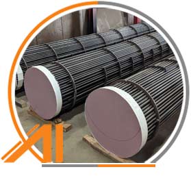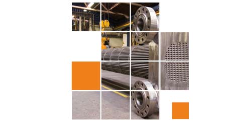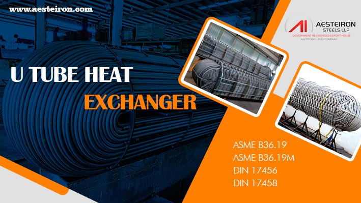
A U-tube heat exchanger is a type of shell and tube heat exchanger commonly used in industries such as chemical and petrochemical sectors. It is designed with a unique U-shaped tube bundle that allows for unlimited thermal expansion, making it ideal for applications where large temperature differences exist between the two fluids involved.
The U-tube design helps absorb expansion and contraction without creating stress on the tubes, ensuring long-term durability and performance. This makes it particularly suitable for high-temperature and high-pressure environments.
Table of contents
- U Tube Heat Exchanger Specification
- U Type Heat Exchanger Function
- U Tube Bundle Heat Exchanger Features
- U Tube Heat Exchanger Design
- U Tube Type Heat Exchanger Diagram
- U Tube VS Straight Tube Heat Exchanger
- Difference Between Floating Head and U Tube Heat Exchanger
- U Tube Condenser Applications
- U Tube Shell and Tube Benefits
- U Tube Exchanger Advantages
- Disadvantages of U-Tube Heat Exchanger
- U Tube Heat Exchanger Calculation
- Cross Over Temperature of U Tube Shell and Tube
Key Features and Functions of U-Tube Heat Exchangers
U Tube Heat Exchanger Specification
| U Tube Heat Exchanger Size |
- 0.010 to 1.500 inch OD
- 0.254 to 38.1 mm OD
|
| Manufacturing Type |
- Seamless
- Welded
- ERW
- Fabricated
|
| Major parts |
- Front Header
- Rear Header
- Tube bundle
- Shell
|
| Dimensions Standard |
- ASME B16.9
- MSS-SP-43
- ASME B16.28
|
| Manufacturing Method |
- Hot Finished
- Cold Finished
|
| Material |
- Stainless Steel
- Duplex & Super Duplex Steel
- Carbon Steel
- Alloy Steel
- Nickel Alloy
|
| Certificates |
- MTC EN 10204 3.1/3.2
- 100% Radiography Test Report
- Raw Materials Certificate
- Third Party Inspection Report
- NACE MR0175
- NACE TM-0284
- NACE MR0103
- ISO 15156
|
| Origin |
- Japanese
- Korean
- Indian
- Russian
- Ukraine
- USA
- European
|
| Application |
- High-temperature
- Low-temperature
- Very high pressure
|
| Srface Treatments |
- Precleaned
- Cleaned
- Passivated
- Pickled
|
| Short Radius Elbow Standard |
|
| Finish |
- 180 grit polished
- Matt finish
- 320 grit
- Mirror
- Solution annealed
- Annealed & Pickled
- No.4
- 2B
- Cold Drawn
- BA polishing
- 400 grit
- Bright Annealed
- 600 grit
|
| Value Added Services |
- Cutting
- Polishing
- Threading
- Beveling
|
How U-Tube Heat Exchangers Work
U Type Heat Exchanger Function
A U-tube heat exchanger transfers heat between two fluids by allowing one fluid to flow through the U-shaped tubes while the other flows around them inside the shell. This design is particularly effective in high-temperature and high-pressure environments due to its robust structure and ability to handle thermal expansion.
U Tube Bundle Heat Exchanger Features
- Excellent heat transfer efficiency
- Fixed at both ends, allowing unidirectional flow
- Easy to maintain and clean
- Capable of handling high temperatures and pressures
- Compact and space-efficient design
Efficient and Durable U-Tube Heat Exchanger Design
The U-tube heat exchanger is engineered to maximize heat transfer while minimizing energy consumption and operational costs. It offers strong pressure resistance and superior heat exchange performance, making it an ideal choice for industrial applications requiring reliability and efficiency.
U Tube Heat Exchanger Design

Understanding the Parts and Working Principle
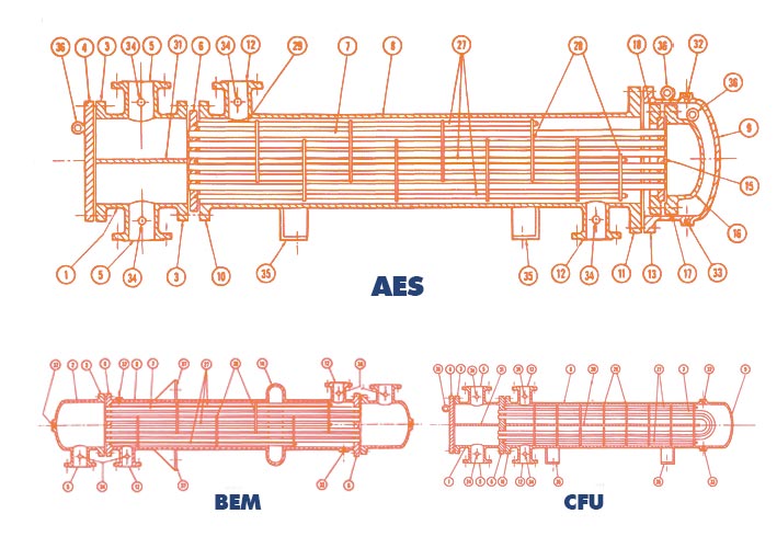
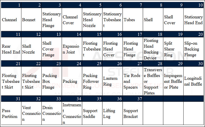
The working principle of a U-tube shell and tube heat exchanger relies on the arrangement of tubes within a shell to facilitate heat transfer. The following diagram provides a detailed view of the components and how they function together.
U tube type heat exchanger Diagram
U Tube VS Straight Tube Heat Exchanger
| Feature |
U-Tube |
Straight |
| Construction |
Compact and robust |
Simpler |
| Design |
Fixed at both ends |
Bundled in a shell |
| Cost |
High |
Low |
| Thermal Expansion |
More |
Less |
| Heat Transfer Area |
Good |
Better |
| Maintenance |
More |
Easier to maintain |
| Space Requirements |
Compact |
Bulkier |
| Lifespan |
Longer |
Varies with design |
Difference Between Floating Head and U Tube Heat Exchanger
| Feature |
Floating Head Heat Exchanger |
U-Tube Heat Exchanger |
| Design |
One end is fixed and the other is free or movable |
Fixed at both ends |
| Maintenance |
Easier |
More challenging |
| Heat Transfer Area |
Larger |
Efficient |
| Space Requirements |
Bulkier |
Compact |
| Cost |
High |
Low |
| Lifespan |
Long |
Robust |
U-Type Heat Exchangers in Petroleum and Chemical Industries
Heat exchangers are essential for transferring heat between two separate channels, either directly or through a barrier. In petroleum and chemical machinery, U-type heat exchangers are widely used because of their compact design, high heat transfer efficiency, and ability to withstand high pressure. These features help reduce the risk of failure and ensure safe operation under harsh conditions.
U Tube Condenser Applications
- Pressure Vessels
- High Pressure Equipments
- Cryogenic Pressure Vessels
- Boilers
- Air Cooler Tubes
- Tube Sheets of Heat Exchangers
- Refineries
- Air Pre Heater
- Fertilizer Plants
- Chemical Factories
- HVAC Systems
U Tube Shell and Tube Benefits
- High Efficiency
- Enhanced Heat Transfer
- Compact Design
- Less Maintenance
- Versatility
- Excellent Durability
- Cost Effectiveness
- Easy to Install
Advantages and Disadvantages of U-Tube Heat Exchangers
U Tube Exchanger Advantages
- Recycled and environmentally friendly
- Energy-saving design
- Wide range of configurations available
- Cost-effective over time
- Available in various materials
- Space-saving designs
- Good thermal compensation
- Easy maintenance
- Can handle different flow rates, fluids, and temperatures
Disadvantages of U-Tube Heat Exchanger
- Limited suitability for extreme temperature ranges
- Potential for warping due to thermal stress
- Requires more installation space
- Needs regular cleaning
- More complex construction
- Higher risk of internal leakage
U Tube Heat Exchanger Calculation

Cross Over Temperature of U Tube Shell and Tube
| Temperature |
Water |
Oil |
| Outlet |
51.5 |
50 |
| Inlet |
30 |
80 |
| Flow Rate |
15 L/min |
25 L/min |
CNC Machined Plastic Processing
CNC Prototype Service,CNC Machining Prototype Plastic Processing,Plastic Products Machining Services,Precision CNC Machining Services
Ningbo Jiongke Technology Co., Ltd , https://www.processingmfg.com


